1) With the exception of the knock sensor wire, all the wiring can be done inside the passenger compartment. The SafeGuard control unit must be mounted inside the passenger compartment. We recommend mounting it near the factory ECU.
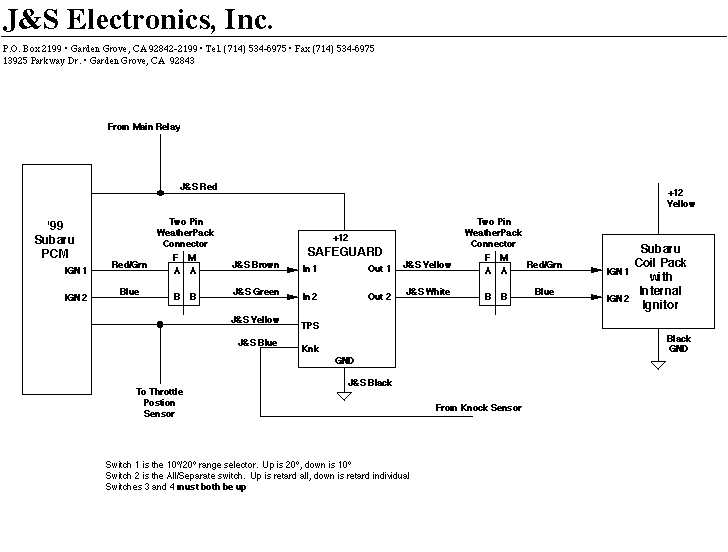
2) Using the factory wiring diagram, look for the two ignition drive signals from the ECU. Label them arbitralily "1" and "2".
Cut them at a convenient point. On the ECU side of the cut wires, install a two pin Female Weatherpack connector. Insert the wire labeled "1" into terminal "A", and the wire labeled "2" into terminal "B".
3) On the engine side of the cut wires, install a two pin Male Weatherpack connector. Insert the wire labeled "1" into terminal "A", and the wire labeled "2" into terminal "B".
4) Route the J&S Brown (input 1) and J&S Green (input 2) wires near the two pin Female Weatherpack connector that you just installed in step 2. Cut them to length and install a mating Male Weatherpack connector. Insert the J&S Brown wire into terminal "A", and the J&S Green wire into terminal "B".
5) Route the J&S Yellow (output 1, not the Yellow TPS wire) and J&S White (output 2) wires near the two pin Male Weatherpack connector that you just installed in step 3. Cut them to length and install a mating Female Weatherpack connector. Insert the J&S Yellow wire into terminal "A", and the J&S White wire into terminal "B".
6) Using the factory wiring diagram, locate the TPS wire. Route the J&S Yellow TPS wire near the factory TPS wire. For now, leave the J&S Yellow wire disconnected.
7) Cut to length and splice the J&S Red wire to the ECU power.
8) Cut to length and connect the J&S Black wire to ECU ground.
9) Feed the J&S Blue knock sensor wire through an existing grommet in the firewall.
10) Install the Knock sensor adapter bolt into the hole on the front of the engine block. Do not torque it more than 15 ft.-lbs.
11) Note: This unit is calibrated for a GM sensor. Do not connect to factory knock sensor. Screw the knock sensor into the adapter bolt and torque it to 14 lbs.
12) Plug the knock sensor connector onto the sensor. Route the J&S Blue wire down to the sensor. Crimp on the appropriate terminal and connect to the sensor. Use some of the small diameter flex loom to cover the sensor wire.
13) Mode Switches: Set the Mode Select switches at the front of the unit as follows: Switch 1 is the 10°/20° range switch. Down is 10° max retard, up is 20° max retard. For now, leave it up. Switch 2 is the retard all/retard separate switch. Temporarily set switch 2 up. Switches 3 and 4 must both be UP.
14) STATUS LED: If the unit is receiving trigger pulses, the Status LED will blink during cranking. If it doesn’t blink, the engine will not start. Once you have the car running on the J&S unit, you are ready to test the knock sensor. Set the sensitivity control to mid-range, and hold the RPM to at least 1500. You should be able to hear the engine slow down as you tap rapidly on the knock sensor with a screwdriver. You can also see it retard with your timing light. This would be a good time to check your timing, and reset it if necessary. Once you have verified that the unit will retard, set mode select switch #2 down. This returns the unit to the individual cylinder retard mode.
15) TPS wire: The J&S Yellow wire can now be connected to the throttle position sensor wire. The signal voltage increases with increasing throttle. The unit is not "armed" to retard until the signal voltage goes above 1.75 volts. If the Yellow wire is left unhooked, the unit will "self arm". Deceleration and light engine loads can produce piston slap that the unit may interpret as knock. For this reason, we do not recommend leaving the Yellow wire disconnected.
16) Now you are ready for your test drive. A common mistake is to set the sensitivity control to maximum. This will usually cause the unit to over-retard due to engine noise. We recommend setting it to mid-range and getting the car up to highway cruising speed. Once the Yellow wire is "armed", increase the sensitivity until the unit just starts to retard due to engine noise. This is easiest to do if you have purchased one of our knock retard monitors. If you don't have a monitor, you may be able to feel the unit retard. In any case, give the unit only as much sensitivity as it takes to make the ping go away. Happy motoring!
17) MONITOR: If you don’t have a monitor, but you still want to see exactly what the unit is doing, get a 3.5mm stereo plug from Radio Shack. Plug it into the monitor jack. Temporarily set the All/Sep switch to retard all. Use a volt meter to measure between the sleeve (ground), and the ring. (The tip supplies 12 volts to power the monitor.) The monitor jack outputs a voltage from 0 to 1.3 volts when the unit is retarding.